The objective of this book is to prepare the reader to design
feedback control systems for dynamic systems and to lay the groundwork
for further studies in the area. The design philosophy that we follow
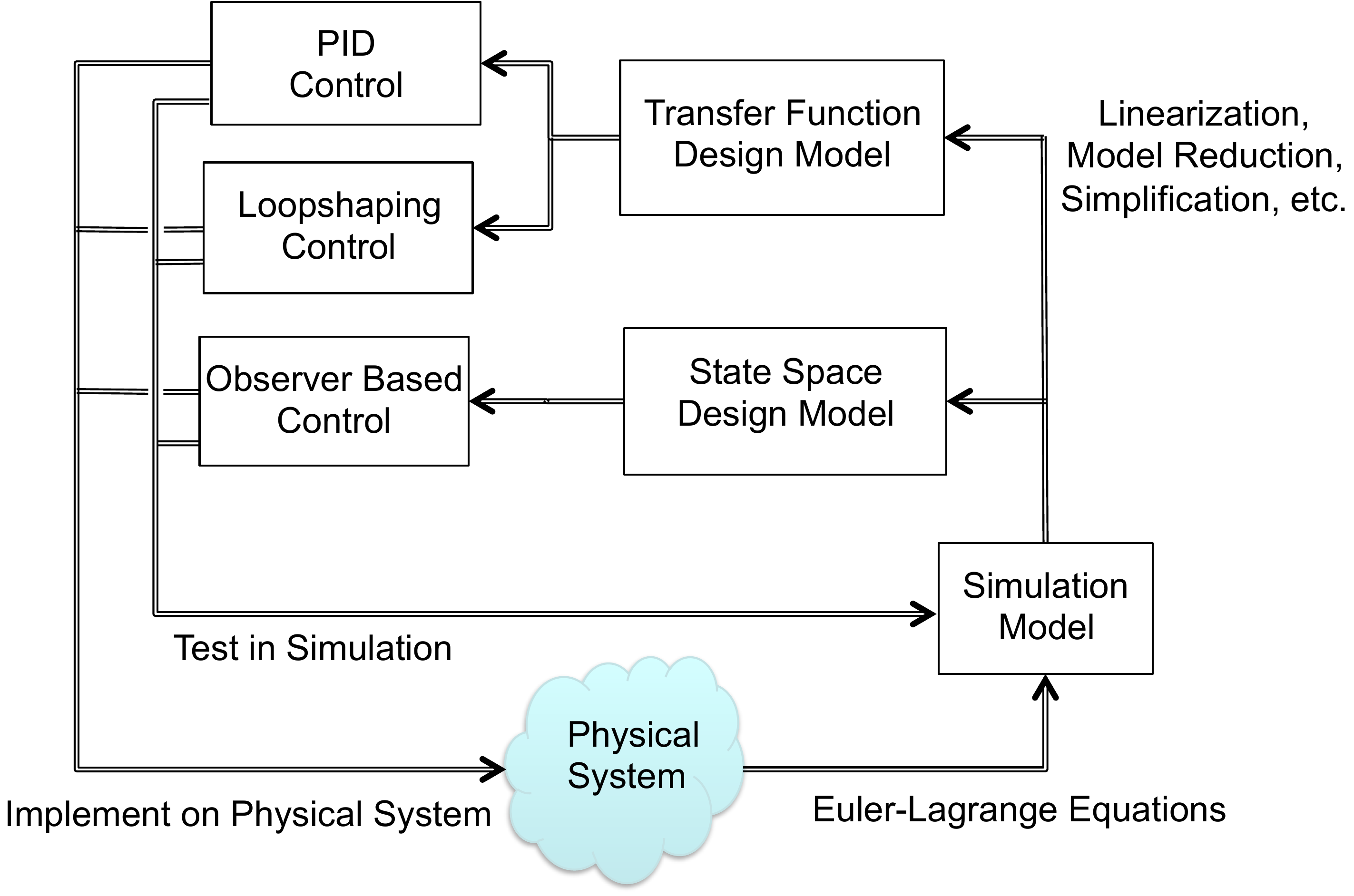
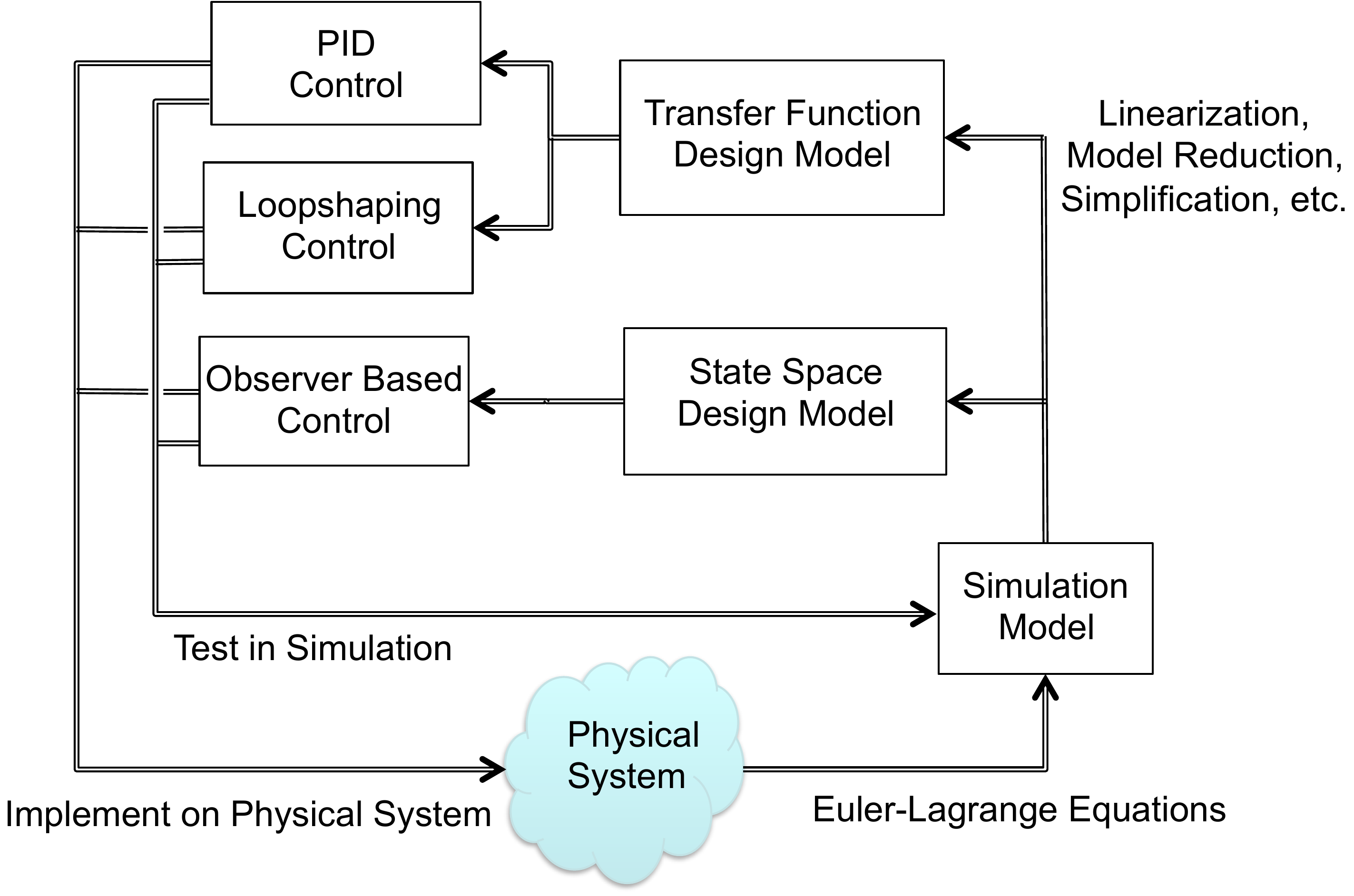
throughout the book is illustrated schematically in
Fig.1.1. The objective is to
design a control system for the “Physical System” shown in
Fig.1.1. The physical system
includes actuators like motors and propellers, and sensors like
accelerometers, gyros, GPS, cameras, and pressure sensors. The first
step in the design process is to model the physical system using
nonlinear differential equations. While approximations and
simplifications will be necessary at this step, the hope is to capture,
in mathematics, all of the important characteristics of the physical
system. While there are many different methods for developing the
equations of motion of the physical systems, in this book we will
introduce one specific method, the Euler-Lagrange method, that is
applicable to a wide variety of mechanical systems. We will, for the
most part, abstract the actuators to applied forces and torques on the
system. Similarly, the sensors will be abstracted to general
measurements of certain physical quantities like position and velocity.
The resulting model is called the Simulation Model as shown in
Fig.1.1. In the design
process, the simulation model
is used for the high fidelity computer simulation of the physical
system. Every control design will be tested thoroughly on the simulation
model. However, the simulation model is only a mathematical
approximation of the physical system, and simply because a design is
effective on the simulation model, we should not assume that it will
function properly on the physical system.
Part I of
the book introduces the Euler-Lagrange method and demonstrates how to
derive simulation models for mechanical systems using this method.
Figure 1.1. The design process. Using principles of
physics, the physical system is modeled mathematically, resulting in the
simulation model. The simulation model is simplified to create design
models that are used for the control design. The control design is then
tested and debugged in simulation and finally implemented on the
physical system.
1.1 Interactive Control
Workflow
Click Figure 1.1
The
diagram below is the same design-process figure, but the major regions
are clickable. Select a region to see how that part of the workflow will
be developed later in the book.
Disturbance experiment
Open-loop and
feedback response to a disturbance
Choose when the
disturbance appears and how large it is. The curves use a simple
first-order plant model: open loop has no current output measurement,
while feedback uses the measured output to drive the response back
toward the desired value. The role of integral action in removing
steady-state disturbance error is developed in Chapter 9, the PID
system-type section.
First-order disturbance comparison for dy/dt = -a
y + u + d. Open-loop operation cannot correct the offset caused by a
constant disturbance. The feedback curve includes the kind of
accumulated-error effect discussed later in Chapter 9, the PID
system-type section, so the output returns to the desired value after
the transient.
The simulation model is typically nonlinear and high order and is too
mathematically complex to be useful for control design. Therefore, to
facilitate design, the simulation model is simplified and usually
linearized to create lower-order design models. For any physical
system, there may be multiple design models that capture certain aspects
of the system that are important for a particular design. In this book
we will introduce the two most common design models used for control
systems analysis and design: transfer-function models and state-space
models. In both cases we will
linearize the system about a particular operating condition. The
advantage of transfer function models is that they capture the frequency
dependence of the input-output relationship in dynamic systems. The
advantage of state-space models is that they are more intuitive and are
better adapted to numerical implementation.
Part II of the book
shows how to linearize the equations of motion and how to create
transfer function and state-space design models.
The next three parts,
Part III–V, introduce
three different control design methods.
Part III shows how to design
Proportional-Integral-Derivative (PID) controllers for second-order
systems. The PID method is the most common control technique used in
industry. It can be understood from both a time-domain and
frequency-domain perspective. The advantage of PID is its simplicity in
design and implementation and the fact that it can be used to achieve
high performance for a surprising variety of systems. However, the
disadvantage of PID control is that stability and
performance can typically only be guaranteed for second-order systems.
Therefore, Part III is focused exclusively on
second-order systems.
In Part IV we
introduce the observer-based control method. Observer-based methods
can be thought of as a natural extension of PID controllers to
higher-order systems. However, observer-based methods are much more
general than PID and can be used to obtain higher performance. In
addition, most observer-based techniques extend to nonlinear and
time-varying systems. The disadvantages of observer-based methods are
that they require a higher level of mathematical sophistication to
understand and use, and they are primarily time-domain methods.
The final design technique, which is covered in
Part V, is the loop
shaping control design method. The loop shaping
method is a frequency domain technique that explicitly addresses
robustness of the system. The loop shaping method is also a natural
extension of PID control to higher-order systems. One of the advantages
of loop shaping techniques is that they can be used when only a
frequency response model of the system is available.
The book is organized around several design studies. For each new
concept that is introduced, we will apply that concept to three specific
design problems. The design problems are introduced in the following
three sections and include a single-link robot arm, a pendulum on a
cart, and a simple satellite attitude control problem. The homework
problems, which are provided in
Part VI, will
follow the same format with problems that are identical to those worked
in the book, but they will be applied to different physical systems. Our
hope is to illustrate the control design process with specific,
easy-to-understand problems. We note, however, that the concepts
introduced in this book are applicable to a much wider variety of
problems than those illustrated in the book. We focus on mechanical
systems, but a similar process (with the exception of the modeling
section) can be followed for any system that can be modeled using
ordinary differential equations. Examples include aerodynamic systems,
electrical systems, chemical processes, large structures like buildings
and bridges, biological feedback systems, economic systems, queuing
systems, and many more.
1.2 Design-Study Preview
Choose a system and identify what control
will need
These cards are a preview. At this point, focus
only on the physical system: what can be actuated, what can be measured,
and what limitation could matter later.
A. Single-link
arm
Likely actuator
Motor torque at
the joint.
Likely measurement
Arm angle and
possibly angular velocity.
Physical
limitation
Motor torque limits and gravity loading.
B. Pendulum on a
cart
Likely actuator
Horizontal
force on the cart.
Likely measurement
Cart
position and pendulum angle.
Physical
limitation
Limited track length and unstable pendulum
motion.
C. Satellite
attitude
Likely actuator
Applied
torque from thrusters or reaction wheels.
Likely
measurement
Attitude angle and angular rate.
Physical limitation
Flexible modes, actuator limits,
and fuel or energy use.
D. Mass-spring-damper
Likely
actuator
Applied force on the mass.
Likely
measurement
Position and possibly velocity.
Physical limitation
Oscillation, damping, and force
limits.
E. Block on
beam
Likely actuator
Beam angle or
torque applied to the beam.
Likely
measurement
Block position and beam angle.
Physical limitation
Beam angle limits and
rolling/sliding assumptions.
F. Planar VTOL
Likely
actuator
Left and right rotor thrusts.
Likely
measurement
Position, altitude, pitch angle, and
rates.
Physical limitation
Rotor saturation,
coupling between pitch and lateral motion, and gravity.
1.3 Design Studies
1.3.1 Design Study: Single Link
Robot Arm
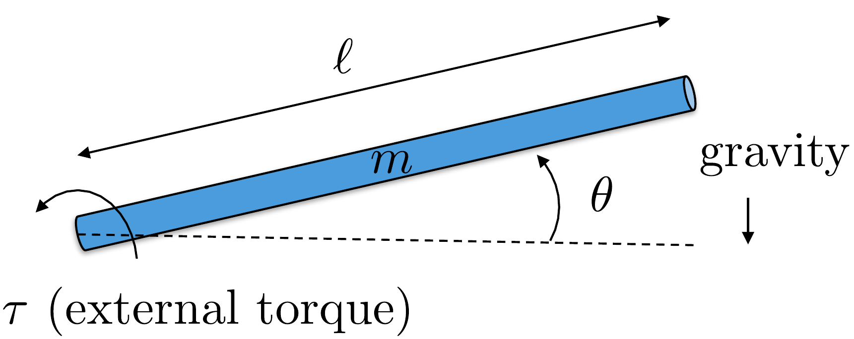
Figure 1.2 shows a
single-link robot arm system. The robot arm has mass \(m\) and length \(\ell\). The angle of the robot is given by
\(\theta\) as measured from horizontal
to the ground. The angular speed of the arm is \(\dot{\theta}\). There is an applied torque
\(\tau\) at the joint. There is also a
damping (or viscous friction) torque that opposes the rotation of the
joint and which can be modeled as \(-b\dot{\theta}\).
The actual physical parameters of the system are \(m=0.5\) kg, \(\ell=0.3\) m, \(g=9.8\) m/s\(^2\), \(b=0.01\) Nms. The torque is limited by
\(\left|\tau\right|\leq 1\) Nm.
Design
Study A orientation
Identify the robot-arm variables before
starting the design sequence
This check is not a worked
solution gate. It is a quick orientation to the coordinate, measured
output, actuator, and physical limitation that appear throughout the
single-link robot-arm design study.
Step 1. Configuration variable
Enter the generalized
coordinate used for the configuration.
Show solution for
Step 1
Answer: The configuration
variable is \(\theta\).
Step 2. Full state versus measured output
For later
state-space chapters, identify the two state variables and the measured
output used for this design study.
Show solution for Step
2
Answer: The state is \(x=(\theta,\dot{\theta})^T\), and the
measured output is \(y=\theta\).
Step 3. Actuation and limitation
Identify the actuator
input and one physical limitation that will matter during control
design.
Show solution
for Step 3
Answer: The actuator is
the applied joint torque \(\tau\).
A key limitation is the torque bound \(|\tau|\leq 1\) Nm; damping or viscous friction also
appears in the model.
Note: The notation identifies the design configuration and the
chapter in which it is used: Example A.4 refers to the
application of approximations in Chapter 4 to linearize design
configuration A. Similarly, Example A.P.6 refers to the
root locus assignment associated with Appendix A.P.6.
1.3.2 Design Study: Pendulum on a
Cart
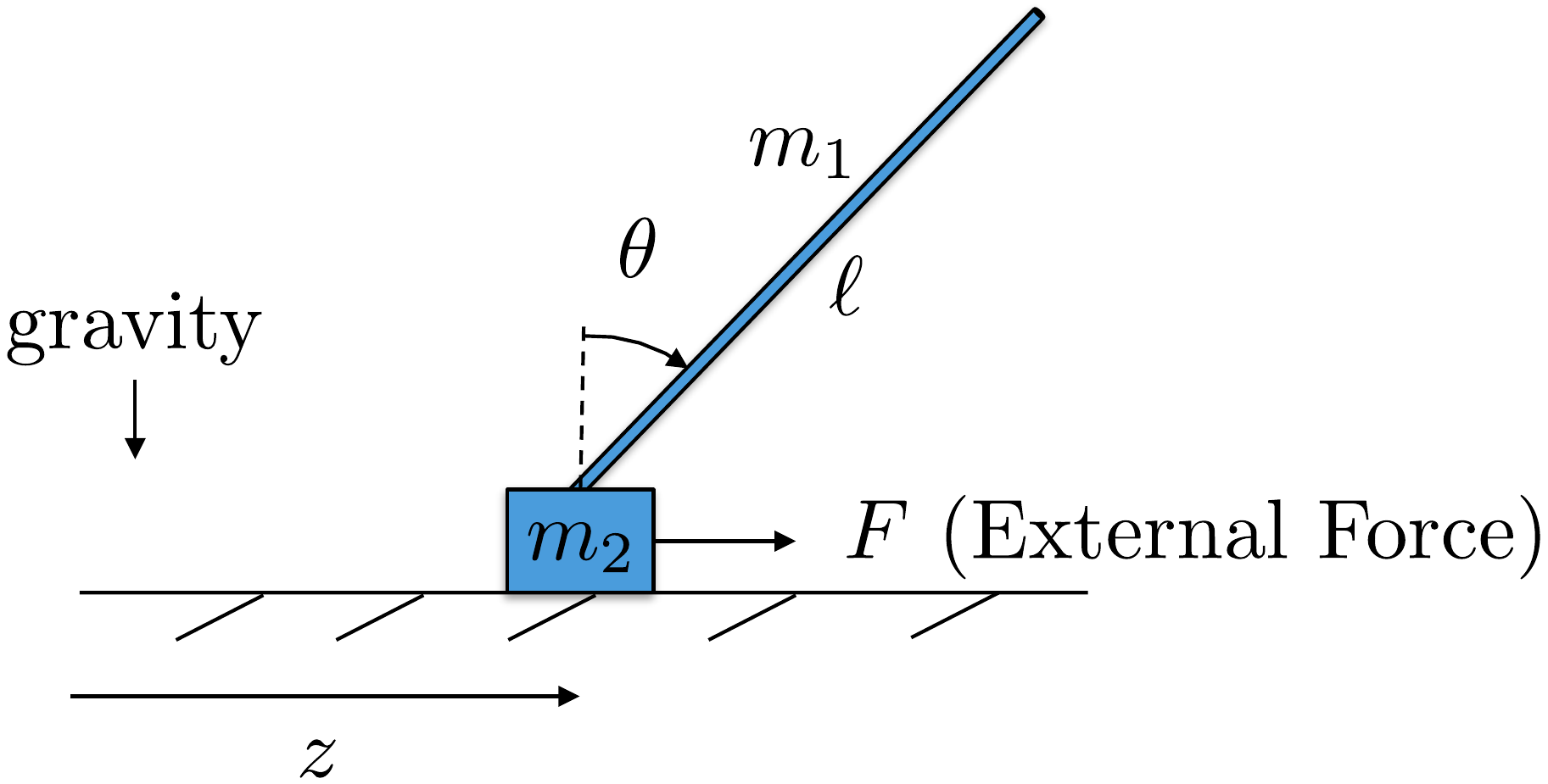
Figure 1.3 shows
the pendulum on a cart system, also called an inverted pendulum. The
position of the cart measured from the origin is \(z\) and the linear speed of the cart is
\(\dot{z}\). The angle of the pendulum
from straight up is given by \(\theta\), and the angular velocity is \(\dot{\theta}\). The rod is of length \(\ell\), and has mass \(m_1\), and is approximated as being
infinitely thin. The cart has mass \(m_2\). Gravity acts in the down direction.
The only applied force is \(F\), which
acts in the direction of \(z\). The
cart slides on a frictionless surface, but air friction produces a
damping force equal to \(-b\dot{z}\).
The physical constants are \(m_1=0.25\) kg, \(m_2=1.0\) kg, \(\ell=1.0\) m, \(g=9.8\) m/s\(^2\), \(b=0.05\) Ns. The force is limited by \(\left|F\right|\leq 5\) N.
Design
Study B orientation
Identify the pendulum variables before
starting the design sequence
This check is not a worked
solution gate. It is a quick orientation to the variables, measurements,
and limitations that appear throughout the pendulum-on-cart design
study.
Step 1. Configuration variables
Enter the two
generalized coordinates used for the configuration.
Show solution for
Step 1
Answer: The configuration
variables are z and θ.
Step 2. Full state versus measured output
For later
state-space chapters, identify the four state variables and the two
measured outputs described in the design study.
Show solution for
Step 2
Answer: The full state is
(z, θ, z, θ)T, while the
measured output used in later chapters is typically (z,
θ)T.
Step 3. Actuation and limitation
Identify the single
actuator and one physical limitation that will matter during control
design.
Show solution
for Step 3
Answer: The actuator is
the horizontal force F on the
cart. Later designs must respect the force limit, limited cart travel,
and the unstable upright pendulum motion.
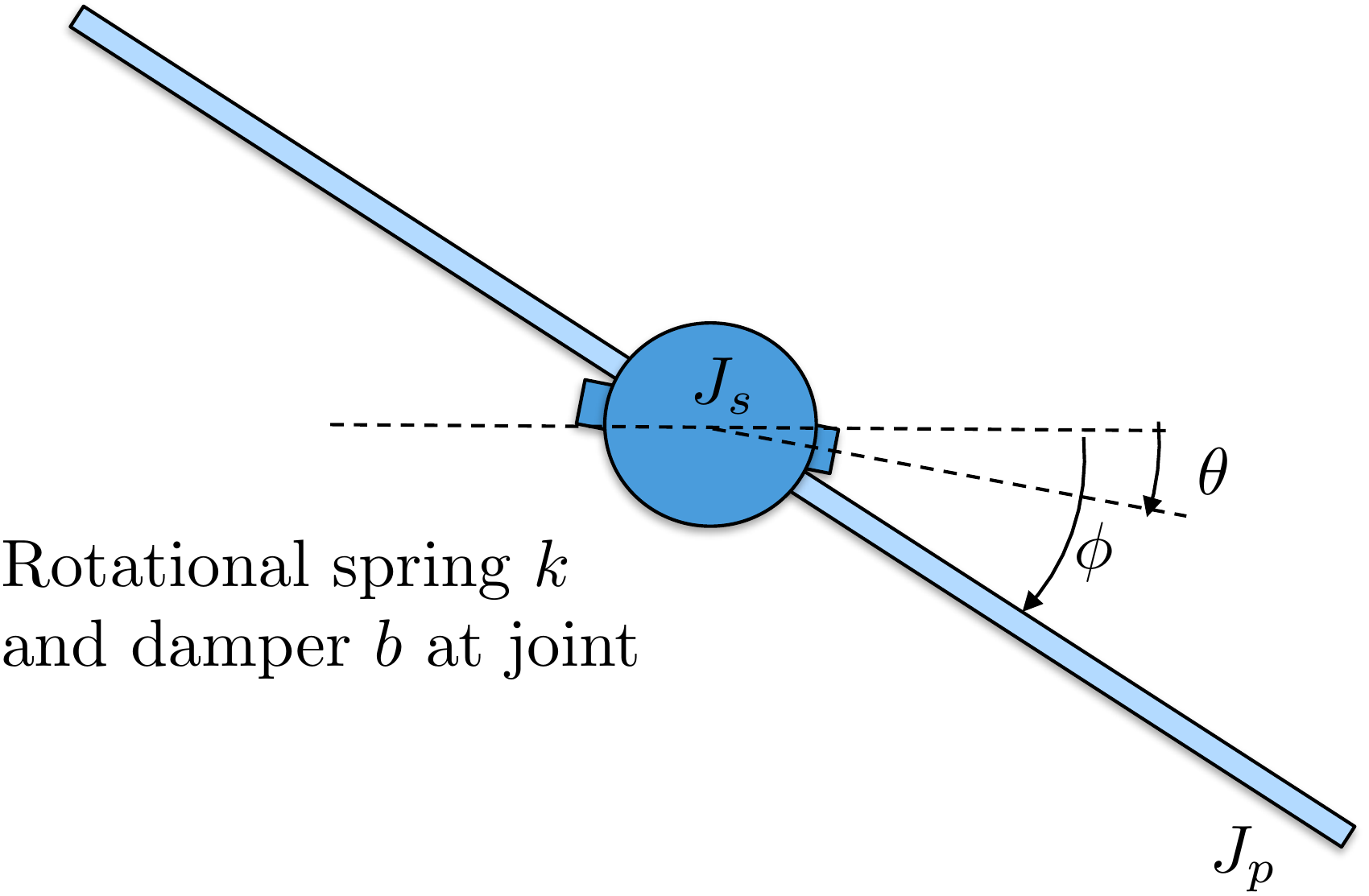
Figure 1.4 shows a simplified version
of a satellite with flexible solar panels. We will model the flexible
panels using a rigid sheet with moment of inertia \(J_p\) connected to the main satellite body
by a torsional compliant element with spring constant \(k\) and damping constant \(b\). The moment of inertia of the satellite
is \(J_s\). The angle of the satellite
body from the inertial reference is \(\theta\) and the angle of the panel from
the inertial reference is denoted as \(\phi\). Thrusters are used to command an
external torque of \(\tau\) about the
axis of the satellite body.
The physical constants are \(J_s=5\) kg m\(^2\), \(J_p=1\) kg m\(^2\), \(k=0.1\) N m, \(b=0.05\) Nms. The torque is limited by
\(\left|\tau\right|\leq 5\) Nm.
Design
Study C guided orientation
Identify the satellite variables
before starting the worked examples
The satellite has a
rigid body and flexible panel. Before using the study in later chapters,
check that you can distinguish the body attitude, panel attitude,
relative panel deflection, and torque input.
Step 1:
Configuration variables
Identify the three variables that
fully describe the satellite and its deflection.
Show solution for Step
1
Answer: The configuration
variables are \(\theta\), \(\phi\), and \(\phi-\theta\).
Step
2. Identify what the actuator directly changes
Show solution for Step
2
Answer: The input is body torque
\(\tau\), applied directly to the
satellite body coordinate \(\theta\).
Step
3. Interpret no flexure
Show solution for Step
3
Answer: No panel flexure means
\(\phi-\theta=0\), so \(\theta=\phi\).
Use these quick checks to test the Chapter 1 workflow vocabulary before
moving on. The short-answer checks are intentionally limited to terms
that can be graded reliably.
Q1. Design
model
Which item best describes the
role of a design model?
Q2. Value of feedback
Why is feedback useful?
Q3. Implementation
Which item is
usually closest to implementation?
Q4. Disturbance response
A disturbance pushes the output away from the
desired behavior. What information does a feedback system need in order
to react?
Q5.
Vocabulary
What is the name for using
measured output to react to error?
Show
solution
Answer: Feedback. Feedback
uses measured output information to respond to
error.
Q6. Model
vocabulary
What kind of model is
simplified for controller design?
Show
solution
Answer: Design model. The
simulation model is simplified into one or more design
models.
Reflection
Prompt
In one or two sentences, explain why the book
separates modeling, design, implementation, and validation.
Show
guidance
Guidance: A strong answer
should mention that each step serves a different purpose and that
success in simulation does not guarantee success on the physical
system.
Q7.
Model roles
A team has a detailed
nonlinear simulator and a simpler linear model used to choose feedback
gains. Which artifact is the design model?
Q8. Feedback information
A wind gust pushes an aircraft away from the
commanded attitude. What information is essential for feedback to
correct the error?