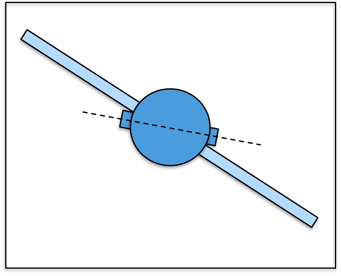
In Part III we focused on designing
feedback control systems for second-order systems. Since second-order
systems have two poles, we saw that it is possible to use feedback
control with two gains to place the closed-loop poles at any desired
location. In
Chapter 14 of this book we will see
that for an \(n^{th}\) order system it
is possible to arbitrarily place the closed-loop poles, but that this
will require \(n\) feedback
gains. In that sense, the
full state feedback controllers that we will derive in
Chapter 14 are a generalization of PD
control to higher-order systems. This generalization is most easily
accomplished using the state-space model of the system derived in
Chapter 9. In fact, the
state-space model leads to efficient numerical routines for designing
and implementing the feedback controller.
In
Chapter 15 we show how
integral control can be added to the
state feedback controllers designed in
Chapter 14. The method introduced in
Chapter 15 has a significant
advantage over the integrator tuning method discussed in
Chapter 13 in the sense
that tuning the integral gain will not impact the other closed-loop
poles and therefore allows for greater design flexibility.
We saw in
Chapter 13 that in order to
implement PD/PID control, the derivative of the output needs to be
reconstructed using a digital differentiator. The generalization of
this idea to state feedback control is that the full state of the system
must be reconstructed. The tool that we will use to reconstruct the
system state is called an observer. The observer design problem
will be discussed in
Chapter 16.
It turns out that observers can be used in a variety of different
contexts outside of feedback control. In particular, observers can be
used to solve target tracking problems and to estimate the system
parameters of complex dynamic systems. In the setting of feedback
control where unknown input and output disturbances act on the system,
observers can be used to estimate the unknown disturbances. In
Chapter 17 we will show how to
design the observer to estimate both the system state and the unknown
constant input disturbance. We will also show that estimating the input
disturbance is mathematically and functionally similar to adding an
integrator.
The design tools developed in
Part IV of this
book use state-space models and require the use of linear algebra and
matrix analysis. A brief review of linear algebra concepts that will be
used in Part IV are given
in Appendix 31.
11 Full State Feedback
11.1 Theory
In this chapter we will show how to use full state feedback to
stabilize a linear time-invariant system represented in state-space
form. Recall from
Section 9.1.2, that for state-space equations
given by \begin{align}
\dot{x} &= Ax + Bu
\tag{11.1}\\
y &= Cx + Du,
\tag{11.2}
\end{align} the poles of the system are the eigenvalues of
\(A\), or in other words, the roots of
the open-loop characteristic equation \[\Delta_{ol}(s) = \det(sI-A) = 0.\]
The matrix \(A\) is called the state-interaction
matrix because it specifies
how the states interact with each other. The basic idea behind full
state feedback is to use the feedback signal to change the interaction
matrix so that the poles are in specified locations. A full state
feedback controller is given by \[\tag{11.3}
u = -Kx + \nu,\] where \(K\in\mathbb{R}^{m\times n}\) are the
feedback gains, and \(\nu\) will be a
signal that is specified later.
Using 11.3
in Equation 11.1 results
in the closed-loop state-space equations \begin{align}
\dot{x} &= Ax + B(-Kx+\nu) = (A-BK)x + B\nu
\tag{11.4}\\
y &= Cx,
\tag{11.5}
\end{align} where the interaction matrix is now \(A-BK\), and so the closed-loop
poles will be given by the
eigenvalues of \(A-BK\), or in other
words, the roots of the closed-loop characteristic equation \[\Delta_{cl}(s) = \det(sI-(A-BK))=0.\] A
natural question that will be addressed in the remainder of this section
is how to select \(K\) so that the
closed-loop characteristic equation is equal to a desired closed-loop
characteristic polynomial \(\Delta_{cl}^d(s)\), where the designer
selects the roots of \(\Delta_{cl}^d(s)=0\) to achieve the desired
closed-loop performance.
Section 9.1.2 showed that the state-space
model given by
Equations 11.1–11.2 is
equivalent to the transfer function model given by \[\tag{11.6}
Y(s) = C(sI-A)^{-1}B U(s).\] While the mapping from state-space
model to transfer function model is unique, the reverse is not true. In
fact, there are an infinite number of state-space models that correspond
to a particular transfer function model. Accordingly, we say that a
state-space model is a realization of the transfer function
model, if it produces the same input-output behavior when the initial
conditions are zero.
In particular, define the change of variables \[\tag{11.7}
z = P^{-1}x,\] where \(P\) is an
invertible matrix. Then \begin{align}
\dot{z} &= P^{-1}\dot{x} = P^{-1}(Ax+Bu) = P^{-1}APz + P^{-1}B u
\tag{11.8}\\
y&= Cx = CPz
\tag{11.9}
\end{align} is an alternative state-space representation of
system 11.1-11.2. To
show that these two representations have the same input-output behavior,
or in other words, the same transfer function, note from
Equation 11.6
that the transfer function of
system 11.8-11.9
is \[\begin{aligned}
Y(s) &= \left( CP(sI-P^{-1}AP)^{-1}P^{-1}B \right) U(s) \\
&= \left( CP(sP^{-1}P-P^{-1}AP)^{-1}P^{-1}B\right) U(s) \\
&= \left( CP(P^{-1}(sI-A)P)^{-1}P^{-1}B \right) U(s) \\
&= \left( CPP^{-1}(sI-A)^{-1}PP^{-1}B \right) U(s) \\
&= \left( C(sI-A)^{-1}B \right) U(s),
\end{aligned}\] which is identical to
Equation 11.6.
Therefore,
Equations 11.1-11.2 and
Equations 11.8-11.9
are realizations of the same system.
11.1.1 State-Space Realization in
Control Canonic Form
In this section, we will derive one specific state-space realization
for single-input single-output transfer functions, where the state
feedback problem is particularly simple. The realization that we derive
below is called the control canonic form of the system.
Consider the general SISO monic transfer function model given by
\[\tag{11.10}
Y(s) = \frac{b_ms^m + b_{m-1}s^{m-1} + \dots + b_1 s + b_0}{s^n +
a_{n-1}s^{n-1} + \dots + a_1 s + a_0} U(s),\] where \(m<n\). The block diagram of the system
is shown in
Fig.11.1.
Figure 11.1. General transfer function for a SISO
system.
The first step in deriving the control canonic state-space equations
is to artificially decompose the transfer function as shown in
Fig.11.2, where the
numerator polynomial and the denominator polynomial appear in separate
cascaded blocks, and where \(Z(s)\) is
an artificial intermediate variable.
Figure 11.2. General transfer function for a SISO
system decomposed into state dynamics and output dynamics.
In the \(s\)-domain, the equations
corresponding to
Fig.11.2 can be
written as \[\begin{aligned}
Z(s) &= \frac{1}{s^n + a_{n-1}s^{n-1} + \dots + a_1 s + a_0} U(s) \\
Y(s) &= (b_ms^m + b_{m-1}s^{m-1} + \dots + b_1 s + b_0) Z(s).
\end{aligned}\] Taking the inverse Laplace transform of these
equations gives \begin{align}
\frac{d^nz}{dt^n} &= u(t) - a_{n-1}\frac{d^{n-1}z}{dt^{n-1}} -
\dots - a_1 \dot{z} - a_0 z(t)
\tag{11.11}\\
y(t) &= b_m\frac{d^mz}{dt^m} + b_{m-1}\frac{d^{m-1}z}{dt^{m-1}} +
\dots + b_1 \dot{z} + b_0 z(t).
\tag{11.12}
\end{align}
The next step in the derivation of the state-space equations is to
draw the analog computer implementation of
Equations 11.11
and 11.12,
which is shown in
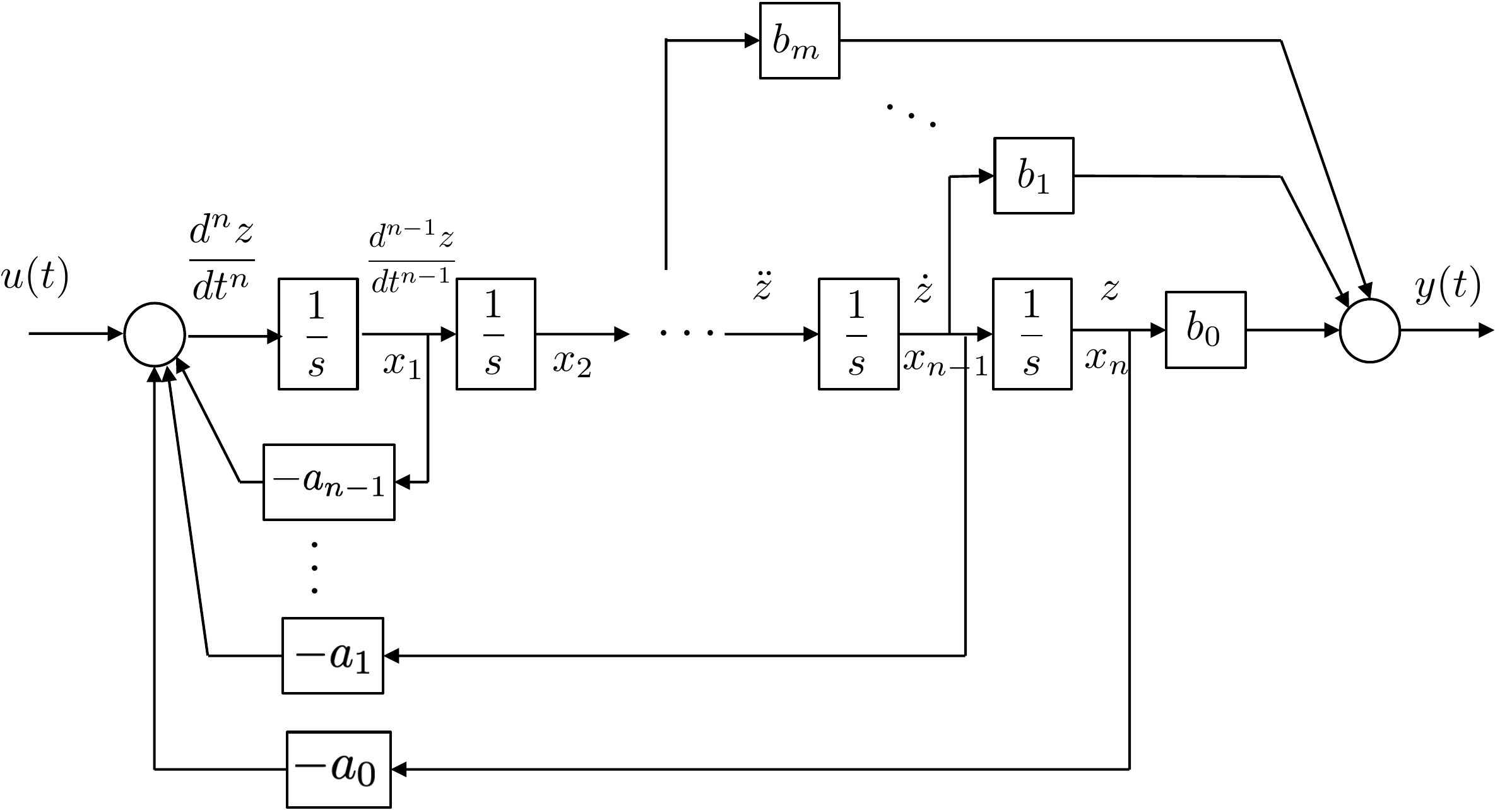
Fig.11.3.
Figure 11.3. Block diagram showing the analog computer
implementation of Equations 11.11
and 11.12.
Labeling the output of the integrators as the state variables \(x_1, \dots, x_n\), as shown in
Fig.11.3, we
can write the state-space equations as \begin{align}
\begin{pmatrix} \dot{x}_1 \\ \dot{x}_2 \\ \vdots \\ \dot{x}_n
\end{pmatrix}
&= \begin{pmatrix}
-a_{n-1} & -a_{n-2} & \dots & -a_1 & -a_0 \\
1 & 0 & \dots & 0 & 0 \\
0 & 1 & \dots & 0 & 0 \\
\vdots & & \ddots & & \vdots \\
0 & 0 & \dots & 1 & 0
\end{pmatrix}
\begin{pmatrix} x_1 \\ x_2 \\ \vdots \\ x_n \end{pmatrix}
+ \begin{pmatrix} 1 \\ 0 \\ \vdots \\ 0 \end{pmatrix} u
\tag{11.13} \\
y &= \begin{pmatrix} 0 & \dots & 0 & b_m & \dots
& b_1 & b_0 \end{pmatrix} \begin{pmatrix} x_1 \\ x_2 \\
\vdots \\ x_n \end{pmatrix}
+ 0\cdot u.
\notag
\end{align} In the case when \(m=n\) it is straightforward to show that
the output equation becomes \[y =
\begin{pmatrix} b_{n-1} - b_n a_{n-1}, & \dots & b_1 - b_n a_1,
& b_0 - b_n a_0 \end{pmatrix} \begin{pmatrix} x_1 \\ x_2 \\
\vdots \\ x_n \end{pmatrix}
+ b_n\cdot u.\] We will define the control canonic
realization as \[\begin{aligned}
\dot{x}_c &= A_c x_c + B_c u \\
y &= C_c x_c + Du,
\end{aligned}\] where \begin{align}
A_c &\stackrel{\triangle}{=}\begin{pmatrix}
-a_{n-1} & -a_{n-2} & \dots & -a_1 & -a_0 \\
1 & 0 & \dots & 0 & 0 \\
0 & 1 & \dots & 0 & 0 \\
\vdots & & \ddots & & \vdots \\
0 & 0 & \dots & 1 & 0
\end{pmatrix}
\tag{11.14}\\
B_c &\stackrel{\triangle}{=}\begin{pmatrix} 1 \\ 0 \\ \vdots \\ 0
\end{pmatrix}
\tag{11.15} \\
C_c &\stackrel{\triangle}{=}\begin{cases}
\begin{pmatrix} 0 & \dots & 0 & b_m & \dots
& b_1 & b_0 \end{pmatrix} &\quad m<n \\
\begin{pmatrix} b_{n-1} - b_n a_{n-1}, & \dots & b_1 -
b_n a_1, & b_0 - b_n a_0 \end{pmatrix} &\quad m=n
\end{cases}
\tag{11.16} \\
D &\stackrel{\triangle}{=}\begin{cases}
0 &\quad m<n \\
b_n &\quad m=n
\end{cases}.
\tag{11.17}
\end{align} Note that the negative of the coefficients of the
denominator of 11.10
constitute the first row of \(A_c\),
and that the remainder of \(A_c\) has
ones on the lower off diagonal and zeros in all other elements. Matrices
with this structure are said to be in companion form. The \(B_c\) vector has a single one as its first
element, with the remaining elements equal to zero. The coefficients of
the numerator of
Equation 11.10
are the last \(p\)-elements of \(C_c\).
As an example, suppose that the transfer function model of the system
is given by \[Y(s) = \frac{9s + 20}{s^3 +
6s^2 - 11s + 8}U(s),\] then the control canonic realization of
the system is given by \begin{align}
\begin{pmatrix} \dot{x}_1 \\ \dot{x}_2 \\ \dot{x}_3 \end{pmatrix}
&= \begin{pmatrix}
-6 & 11 & -8 \\
1 & 0 & 0 \\
0 & 1 & 0
\end{pmatrix}\begin{pmatrix} x_1 \\ x_2 \\ x_3 \end{pmatrix}
+ \begin{pmatrix} 1 \\ 0 \\ 0\end{pmatrix} u
\tag{11.18} \\
y &= \begin{pmatrix} 0 & 9 & 20 \end{pmatrix}
\begin{pmatrix} x_1 \\ x_2 \\ x_3 \end{pmatrix}.
\notag
\end{align}
11.1.2 Full State Feedback using
Control Canonic Form
The design of a state feedback controller is particularly easy when
the state-space equations are in control canonic form. The key insight
is that there is a direct relationship between matrices in companion
form, as shown in
Equation 11.14 and
their characteristic polynomial \[\Delta_{ol}(s) = s^n + a_{n-1}s^{n-1} + \dots +
a_1 s + a_0.\] Suppose that we let \[\tag{11.19}
u = -K_cx_c + \nu = -\begin{pmatrix} k_1 & k_2 & \dots &
k_{n-1} & k_n\end{pmatrix} \begin{pmatrix} x_1 \\ x_2 \\ \vdots \\
x_{n-1} \\ x_n \end{pmatrix} + \nu.\] Substituting into
Equation 11.13
and rearranging gives \[\begin{gathered}
\begin{pmatrix} \dot{x}_1 \\ \dot{x}_2 \\ \vdots \\ \dot{x}_n
\end{pmatrix}
= \begin{pmatrix}
-(a_{n-1}+k_1) & -(a_{n-2}+k_2) & \dots &
-(a_1+k_{n-1}) & -(a_0+k_n) \\
1 & 0 & \dots & 0 & 0 \\
0 & 1 & \dots & 0 & 0 \\
\vdots & & \ddots & & \vdots \\
0 & 0 & \vdots & 1 & 0
\end{pmatrix}
\begin{pmatrix} x_1 \\ x_2 \\ \vdots \\ x_n \end{pmatrix}
%
+ \begin{pmatrix} 1 \\ 0 \\ \vdots \\ 0 \end{pmatrix} \nu.
\end{gathered}\] Since the state interaction matrix is still in companion
form, the characteristic polynomial of the closed-loop system is given
by \[\Delta_{cl}(s) = s^n +
(a_{n-1}+k_1)s^{n-1} + \dots + (a_1+k_{n-1}) s + (a_0+k_n).\] If
the desired characteristic polynomial is given by \[\tag{11.20}
\Delta_{cl}^d(s) = s^n + \alpha_{n-1}s^{n-1} + \dots + \alpha_1 s +
\alpha_0,\] then we have that \[\begin{aligned}
a_{n-1} + k_1 &= \alpha_{n-1} \\
a_{n-2} + k_2 &= \alpha_{n-2} \\
\vdots & \\
a_{1} + k_{n-1} &= \alpha_{1} \\
a_0 + k_n &= \alpha_0.
\end{aligned}\] Defining the row vectors \[\begin{aligned}
\mathbf{a}_A &= (a_{n-1}, a_{n-2}, \dots, a_1, a_0) \\
\boldsymbol{\alpha} &= (\alpha_{n-1}, \alpha_{n-2}, \dots, \alpha_1,
\alpha_0) \\
K_c &= (k_1, k_2, \dots, k_{n-1}, k_n),
\end{aligned}\] we have that the feedback gains satisfy \[\tag{11.21}
K_c = \boldsymbol{\alpha}-\mathbf{a}_A,\] where the subscript “c”
is used to emphasize that the gains are in control canonic form.
As an example, consider the state equations given in
Equation 11.18.
The open-loop characteristic polynomial is given by \[\Delta_{ol}(s) = s^3 + 6s^2 - 11 s + 8,\]
with roots at \(-7.5885\), and \(0.7942\pm j0.6507\). Suppose that the
desired closed-loop characteristic polynomial is \[\Delta_{cl}^d(s) = s^3 + 5s^2 + 12 s +
8,\] with roots at \(-1\) and
\(-2\pm j2\), then \(\mathbf{a}_A = (6, -11, 8)\), and \(\boldsymbol{\alpha} = (5, 12, 8)\). The
feedback gains that place the poles at the desired locations are
therefore given by \[K_c =
\boldsymbol{\alpha}-\mathbf{a}_A = (5, 12, 8)-(6, -11, 8) = (-1, 23,
0).\]
11.1.3 Full State Feedback: General
Case
The formula given in
Equation 11.21
assumes that the state-space equations are in control canonic form. It
turns out that the closed-loop eigenvalues cannot always be arbitrarily
assigned to desired locations. When they can, the system \(\dot{x}=Ax+Bu\) is said to be
controllable. In this section we will derive an expression for
the state feedback gains, and we will simultaneously derive a simple
test for determining when the system is controllable.
Recall from
Equations 11.7–11.9
that state-space equations can be transformed using the change of
variables in
Equation 11.7
without modifying the input-output properties of the system. This
implies that the change of variables does not change the characteristic
polynomial. We can verify this fact explicitly as follows: \[\begin{aligned}
\det(sI-P^{-1}AP)
&= \det(sP^{-1}P-P^{-1}AP) \\
&= \det\left(P^{-1}(sI-A)P\right) \\
&= \det(P^{-1})\det(sI-A)\det(P) \\
&= \det(sI-A).
\end{aligned}\]
Therefore, to derive full state feedback gains for the general
state-space equations \[\tag{11.22}
\dot{x}=Ax+Bu,\] the idea is to find a state transformation
matrix \(P\) so that the transformed
system is in control canonic form, i.e., find \(P\) so that \[\tag{11.23}
x_c=P^{-1}x,\] and \[\tag{11.24}
\dot{x}_c = P^{-1}APx_c + P^{-1}B u = A_c x_c + B_c u,\] where
\(A_c\) and \(B_c\) have the form given by
Equations 11.14
and 11.15,
respectively. Therefore, we need to find \(P\) so that \(P^{-1}B = B_c\), and \(P^{-1}AP=A_c\), which are satisfied if and
only if \(B=PB_c\) and \(AP=PA_c\). Let \(P=(\mathbf{p}_1, \mathbf{p}_2, \dots,
\mathbf{p}_n)\), where \(\mathbf{p}_i\in\mathbf{R}^n\) is the \(i^{th}\) column of \(P\). The requirement that \(B=PB_c\) implies that \[B = \begin{pmatrix} \mathbf{p}_1 &
\mathbf{p}_2 & \dots & \mathbf{p}_n \end{pmatrix}
\begin{pmatrix} 1 \\ 0 \\ \vdots \\ 0 \end{pmatrix} =
\mathbf{p}_1.\] Therefore, \(\mathbf{p}_1=B\). The requirement that
\(PA_c=AP\) implies that \[\begin{gathered}
\begin{pmatrix} \mathbf{p}_1 & \mathbf{p}_2 & \dots &
\mathbf{p}_n \end{pmatrix}\begin{pmatrix}
-a_{n-1} & -a_{n-2} & \dots & -a_1 & -a_0 \\
1 & 0 & \dots & 0 & 0 \\
0 & 1 & \dots & 0 & 0 \\
\vdots & & \ddots & & \vdots \\
0 & 0 & \dots & 0 & 0 \\
0 & 0 & \vdots & 1 & 0
\end{pmatrix} \\ = A \begin{pmatrix} \mathbf{p}_1 & \mathbf{p}_2
& \dots & \mathbf{p}_n \end{pmatrix}.
\end{gathered}\] After multiplication, the first \(n-1\) columns can be equated to get \begin{align}
-a_{n-1}\mathbf{p}_1 + \mathbf{p}_2 &= A\mathbf{p}_1
\tag{11.25}\\
-a_{n-2}\mathbf{p}_1 + \mathbf{p}_3 &= A\mathbf{p}_2
\tag{11.26}\\
\vdots \\
-a_1\mathbf{p}_1 + \mathbf{p}_{n} &= A\mathbf{p}_{n-1}.
\tag{11.28}
\end{align}
Equation 11.25, and
the previous conclusion that \(\mathbf{p}_1=B\), implies that \[\mathbf{p}_2 = a_{n-1}B + AB.\] Using this
result in
Equation 11.26 gives
\[\mathbf{p}_3 = a_{n-2}B + a_{n-1} AB +
A^2B.\] We can continue to iteratively solve for each column of
\(P\) until the \((n-1)^{th}\) column, which from
Equation 11.28 is
\[\mathbf{p}_n = a_1B + a_2AB + \dots +
a_{n-1}A^{n-2}B + A^{n-1}B.\] Notice that each column in \(P\) is a linear combination of the elements
\(B\), \(AB\), \(A^2B\), \(\dots\), \(A^{n-1}B\). Accordingly, defining \[\tag{11.29}
\mathcal{C}_{A,B} = \begin{pmatrix} B & AB & A^2B & \dots
& A^{n-1}B\end{pmatrix},\] gives \[\begin{aligned}
\mathbf{p}_1 &= \mathcal{C}_{A,B}\begin{pmatrix} 1, & 0, &
\dots & 0, & 0 \end{pmatrix}^\top, \\
\mathbf{p}_2 &= \mathcal{C}_{A,B}\begin{pmatrix} a_{n-1}, & 1,
& \vdots & 0, & 0 \end{pmatrix}^\top, \\
\vdots &\qquad \vdots \\
\mathbf{p}_n &= \mathcal{C}_{A,B} \begin{pmatrix} a_1, & a_2,
& \vdots & a_{n-1}, & 1 \end{pmatrix}^\top.
\end{aligned}\] Defining the matrix \[\tag{11.30}
\mathcal{A}_A = \begin{pmatrix}
1 & a_{n-1} & a_{n-2} & \dots & a_2 & a_1 \\
0 & 1 & a_{n-1} & \vdots & a_3 & a_2 \\
0 & 0 & 1 & \vdots & a_4 & a_3 \\
\vdots & & & \ddots & \vdots \\
0 & 0 & 0 & \dots & 1 & a_{n-1} \\
0 & 0 & 0 & \dots & 0 & 1
\end{pmatrix},\] gives that the transformation matrix that
converts the system into control canonic form is \[P = \mathcal{C}_{A,B}\mathcal{A}_A.\]
Notice that since \(\mathcal{A}_A\) is
an upper triangular matrix with ones on the diagonal, \(\det(\mathcal{A}_A)=1\), implying that
\(\mathcal{A}_A^{-1}\) always exists.
It is clear that the matrix \(P\) is
invertible with \[P^{-1}=\mathcal{A}_A^{-1}\mathcal{C}_{A,B}^{-1}\]
if and only if \(\mathcal{C}_{A,B}^{-1}\) exists. The matrix
\(\mathcal{C}_{A,B}\) in
Equation 11.29
is called the controllability matrix, and a single input
system is said to be controllable if \(\mathcal{C}\) is invertible. Therefore,
when the original
system 11.22
is controllable, there exists an invertible state transformation matrix
\(P\) so that the change of variables
in Equation 11.23
is well defined and that results in the transformed equations being in
control canonic form via
Equations 11.24.
In control canonic form, the state feedback equation is \[u = -K_cx_c + \nu =
-(\boldsymbol{\alpha}-\mathbf{a}_A)x_c + \nu.\] Using
Equation 11.23
the state feedback control can be expressed in the original states \(x\) as \begin{align}
u &= -(\boldsymbol{\alpha}-\mathbf{a}_A)P^{-1}x + \nu \notag \\
&=
-(\boldsymbol{\alpha}-\mathbf{a}_A)\mathcal{A}_A^{-1}\mathcal{C}_{A,B}^{-1}x
+ \nu \notag \\
&= - Kx + \nu, \tag{11.31}
\end{align} where \[\tag{11.32}
K
\stackrel{\triangle}{=}(\boldsymbol{\alpha}-\mathbf{a}_A)\mathcal{A}_A^{-1}\mathcal{C}_{A,B}^{-1}.\]
Equation 11.32
is called Ackermann’s formula for the feedback
gains. Since \(\mathcal{C}_{A,B}\) is
only square in the single-input case, Ackermann’s formula only holds for
single input systems.
Using the full state feedback control in
Equation 11.31
in the state
equations 11.1-11.2
results in the closed-loop system \[\begin{aligned}
\dot{x} &= (A-BK)x + B\nu \\
y&= Cx.
\end{aligned}\] The resulting transfer function from \(\nu\) to \(y\) is given by \[\tag{11.33}
Y(s) = \left(C(sI-(A-BK))^{-1}B\right)\nu(s).\]
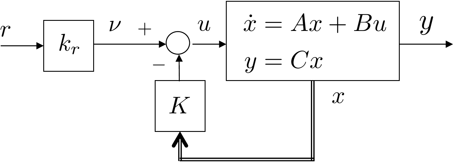
A block diagram of the resulting closed-loop system is shown in
Fig.11.4 where the double
line associated with \(x\) is meant to
imply that the state \(x\) is not
really available. The block diagram also shows the new input \(\nu\). Since the objective is for the
output \(y\) to track the reference
input \(r\), we let \(\nu(t)=k_r r(t)\), as shown in
Fig.11.4. The feedforward
gain \(k_r\) is selected so that the DC
gain from \(r\) to \(y\) is equal to one.
Figure 11.4. Full state feedback with reference input
r.
From
Equation 11.33, the
transfer function from \(R\) to \(Y\) is given by \[\tag{11.34}
Y(s) = \left(C(sI-(A-BK))^{-1}Bk_r\right) R(s),\] and the DC gain
is \[\tag{11.35}
k_{DC} = \lim_{s\to 0} \left[C(sI-(A-BK))^{-1}Bk_r\right] =
-C(A-BK)^{-1}Bk_r.\] Therefore, the DC gain is equal to one if
\[k_r = -\frac{1}{C(A-BK)^{-1}B}.\]
The matrix \(A-BK\) will be invertible
when there are no eigenvalues at zero. Since \(K\) is selected to place the eigenvalues in
the open left half-plane, the matrix will always be invertible, and
\(k_r\) exists. Note that in many
applications, the output measured by the sensors is not the same as the
desired reference output. In other words, the state-space equations may
be given by \[\begin{aligned}
\dot{x} &= Ax + Bu \\
y_r &= C_r x \\
y_m &= C_m x,
\end{aligned}\] where \(y_r\) is
the reference output and \(y_m\) is the measured output. In this case, the
reference gain \(k_r\) is selected to
make the DC gain from \(r\) to \(y_r\) equal to one, or in other words \[\tag{11.36}
k_r = -\frac{1}{C_r(A-BK)^{-1}B}.\]
Chapter 16 will describe observers that use
the measured output \(y_m\) to
reconstruct the state \(x\).
The feedforward gain computed in
Equation 11.36 is for single input systems.
More generally, if the size of the reference output \(y_r\) is equal to the size of the input
vector \(u\in\mathbb{R}^m\), then \(C_r\in\mathbb{R}^{m\times n}\) and \(B\in\mathbb{R}^{n\times m}\), which implies
that the transfer matrix in
Equation 11.34 is
square and has dimension \(m\times m\).
Similarly, the resulting matrix gain \(K_r\in\mathbb{R}^{m\times m}\) will also be
square and from
Equation 11.35
will be equal to \[K_r =
-\left[C_r(A-BK)^{-1}B\right]^{-1}.\]
11.1.4 State Feedback for
Linearized Systems
Suppose that the state-space model is from a linearized
system, i.e., suppose that
\(x\in\mathbb{R}^n\) is the state and
that \(x_e\in\mathbb{R}^n\) is the
equilibrium state, and that \(\tilde{x}=x-x_e\) is the state linearized
around the equilibrium. Similarly, suppose that \(u\in\mathbb{R}^m\) is the input, that \(u_e\in\mathbb{R}^m\) is the input at
equilibrium, and that \(\tilde{u}=u-u_e\) is the input linearized
around equilibrium, and that \(y_r\in\mathbf{R}^p\) is the reference
output, \(y_{re}=C_rx_e\in\mathbf{R}^p\) is the
reference output at equilibrium, and \(\tilde{y}_r=y_r-y_{re}\) is the reference
output linearized about equilibrium, then the linearized state-space
model is given by \[\begin{aligned}
\dot{\tilde{x}} &= A\tilde{x} + B\tilde{u} \\
\tilde{y}_r &= C_r\tilde{x}.
\end{aligned}\] Now suppose that the state feedback design
process is used to find the state feedback controller \[\tag{11.37}
\tilde{u} = -K\tilde{x} + k_r \tilde{r}\] where \(\tilde{r}=r-y_{re}\) is the reference input
around the equilibrium output, and where the eigenvalues of \((A-BK)\) are in the open left half-plane,
and the DC gain from \(\tilde{r}\) to
\(\tilde{y}_r\) is one. The controller
input to the plant is therefore \[\tag{11.38}
u = u_e - K(x-x_e) + k_r(r-y_{re}).\]
11.2 Summary of Design Process -
State Feedback
The state feedback design process can be summarized as follows.
Given the plant \[\begin{aligned}
\dot{x} &= Ax + Bu \\
y_r &= C_rx
\end{aligned}\] and the desired pole locations \(p_1, p_2, \dots, p_n\), find the gains
\(K\) and \(k_r\) so that the feedback controller \[u = -Kx + k_r r\] places the poles at the
desired location and results in a DC gain equal to one.
Step 1.
Check to see if the system is controllable by computing the
controllability matrix \[\mathcal{C}_{A,B} =
[B, AB, \dots, A^{n-1}B]\] and checking to see if \(\text{rank}(\mathcal{C})=n\).
Step 3.
Select the desired closed-loop polynomial \[\begin{aligned}
\Delta_{cl}^d(s) &= (s-p_1)(s-p_2)\cdots(s-p_n) \\
&= s^n + \alpha_{n-1}s^{n-1} + \cdots + \alpha_1 s + \alpha_0,
\end{aligned}\] and construct the row vector \[\boldsymbol{\alpha} = (\alpha_{n-1},
\alpha_{n-2}, \dots, \alpha_1, \alpha_0).\]
Step 4.
Compute the desired gains as \[\begin{aligned}
K &=
(\boldsymbol{\alpha}-\mathbf{a}_A)\mathcal{A}_A^{-1}\mathcal{C}_{A,B}^{-1}
\\
k_r &= \frac{-1}{C_r(A-BK)^{-1}B}.
\end{aligned}\]
Using Python, these steps can be implemented as follows:
import control as cnt
import numpy as np

CC = cnt.ctrb(A,B)

# check for controllability
if np.linalg.matrix_rank(CC) == np.size(A,1):
    print('the system is controllable')
else:
    print('the system is not controllable')

# place the poles at p1, p2, ..., pn
K = cnt.place(A, B, [p1, p2, p3])

# compute reference gain
kr = -1/(C @ np.linalg.inv(A - B @ K) @ B)
11.2.1 Simple example
Given the system \[\begin{aligned}
\dot{x} &= \begin{pmatrix} 0 & 1 \\ 2 & 3 \end{pmatrix} x +
\begin{pmatrix} 0 \\ 4 \end{pmatrix} u \\
y_r &= \begin{pmatrix} 5 & 0 \end{pmatrix} x
\end{aligned}\] find the feedback gain \(K\) to place the closed-loop poles at \(-1\pm j\), and the reference gain \(k_r\) so that the DC gain is one.
Step 1.
The controllability matrix is given by \[\mathcal{C}_{A,B} = [B, AB] = \begin{pmatrix} 0
& 4 \\ 4 & 12 \end{pmatrix}.\] The determinant is \(\det(\mathcal{C})=-16\neq 0\), therefore
the system is controllable.
Step 2.
The open-loop characteristic polynomial is \[\Delta_{ol}(s)=\det(sI-A) = \det\begin{pmatrix} s
& -1 \\ -2 & s-3 \end{pmatrix} = s^2 - 3s -2,\] which
implies that \[\begin{aligned}
\mathbf{a}_A &= (-3, -2) \\
\mathcal{A}_A &= \begin{pmatrix}
1 & -3 \\ 0 & 1
\end{pmatrix}
\end{aligned}\]
Step 3.
The desired closed-loop polynomial is \[\Delta_{cl}^d(s) =
(s+1-j)(s+1+j)=s^2+2s+2,\] which implies that \[\boldsymbol{\alpha} = \begin{pmatrix}2, &
2\end{pmatrix}.\]
Use the same procedure as the simple example above. For the system
below, compute each quantity in order and click Check
before moving on. The solution for each step is revealed only after that
step is checked.
Desired closed-loop poles: -2 ±
j.
Step 1. Controllability matrix
Compute the controllability matrix. Enter the four entries row by row
and the determinant.
CA,B =
Show solution
Answer: B = (0, 2)T and AB = (2,
4)T, so CA,B = (0, 2; 2, 4) and
det(CA,B) = -4. The system is controllable.
Step 2. Open-loop characteristic polynomial
Find the open-loop characteristic polynomial coefficients.
a =
Show solution
Answer: det(sI - A) = s2 - 2s - 1, so a =
(-2, -1).
Step 3. Desired closed-loop polynomial
Find the desired closed-loop characteristic polynomial from the
specified poles.
α =
Show solution
Answer: The desired polynomial is s2 + 4s +
5, so alpha = (4, 5).
Step 4. State-feedback gain
Compute the state-feedback gain using the pole-placement method from
this section. Enter the two entries of K.
K =
Show solution
Answer: alpha - a = (6, 6), Acal-1 = (1, 2;
0, 1), and CA,B-1 = (-1, 0.5; 0.5, 0), giving K =
(3, 3).
Step 5. Check A - BK
Use your K to form A - BK. Enter the four entries row by row.
A - BK =
Show solution
Answer: BK = (0, 0; 6, 6), so A - BK = (0, 1; -5, -4).
Its characteristic polynomial is s2 + 4s + 5.
Step 6. Reference gain
Compute the reference gain for unit steady-state tracking.
The objective of this problem is to implement a state feedback
controller using the full state. Start with the simulation files
developed in
Homework 3.1.13.
(a) Select the closed-loop poles as the roots of the equation \(s^2 + 2\zeta\omega_n + \omega_n^2 = 0\),
where \(t_r = 0.4890\) and \(\zeta = 0.707\). These values may be
different from the parameters found in
Homework 3.1.11.
(b) Add the state-space matrices \(A\),
\(B\), \(C\), \(D\)
derived in
Homework 3.1.9 to your param file.
(c) Verify that the state-space system is controllable by checking that
\(\text{rank}(\mathcal{C}_{A,B})=n\).
(d) Find the feedback gain \(K\) so that
the eigenvalues of \((A-BK)\) are equal
to the desired closed-loop poles. Find the reference gain \(k_r\) so that the DC gain from \(\theta_r\) to \(\theta\) is equal to one. Note that if you
used the exact same pole values from
Homework 3.1.11, \(K=(k_p, k_d)\) where \(k_p\) and \(k_d\) are the proportional and derivative
gains found in that problem. Why?
(e) Modify the control code to implement the state feedback controller.
Assume that you have access to the entire state.
Design Study A guided exercise
Design full-state feedback
Start from the Chapter 6
state-space model and check controllability before computing
gains.
Step 1. Controllability matrix
Show solution for
Step 1
Answer: The second-order arm
model is controllable because \(\operatorname{rank}(\mathcal{C})=2\).
Step 2. Desired polynomial
Show solution for Step
2
Answer: Match \(s^2+2\zeta\omega_n s+\omega_n^2\) to the closed-loop
characteristic polynomial.
Step 3. Reference gain purpose
Show solution for
Step 3
Answer: The reference gain
scales the command so the closed-loop system tracks a constant reference
with the desired DC gain.
Pseudocode
The complete solution includes
state-feedback controller code. Before opening it, outline how you would
compute the state-feedback input from \(x\), \(K\), and
\(k_r\).
This prompt is
ungraded. It is intended to connect the gain calculation to the
implementation code in the complete solution.
Complete solution
From HW 3.1.9, the state-space
equations for the single-link robot arm are given by \[\begin{aligned}
\dot{x} &= \begin{pmatrix} 0 & 1.0000 \\ 0 & -0.667
\end{pmatrix}x + \begin{pmatrix} 0 \\ 66.667 \end{pmatrix} u \\
y &= \begin{pmatrix}1 & 0 \end{pmatrix}x.
\end{aligned}\]
Step 1.
The controllability matrix is therefore \[\mathcal{C}_{A,B} = [B, AB] = \begin{pmatrix} 0
& 66.6667 \\ 66.6667 & -44.44440 \end{pmatrix}.\] The
determinant is \(det(\mathcal{C}_{A,B})=-4444\neq 0\),
therefore the system is controllable.
Step 2.
The open-loop characteristic polynomial is \[\Delta_{ol}(s)=\text{det}(sI-A) =
\text{det}\begin{pmatrix} s & -1 \\ 0 & s+0.667 \end{pmatrix} =
s^2 +0.667 s,\] which implies that \[\begin{aligned}
\mathbf{a}_A &= (0.667, 0) \\
\mathcal{A}_A &= \begin{pmatrix}
1 & 0.667 \\ 0 & 1
\end{pmatrix}
\end{aligned}\]
Step 3.
The desired closed-loop polynomial is \[\Delta_{cl}^d(s) = s^2+2\zeta\omega_n s +
\omega_n^2=s^2+6.3616s+20.2408\] which implies that \[\boldsymbol{\alpha} = (6.3616,
20.2408).\]
Step 4.
The gains are therefore given as \[\begin{aligned}
K &=
(\boldsymbol{\alpha}-\mathbf{a}_A)\mathcal{A}_A^{-1}\mathcal{C}_{A,B}^{-1}
= \begin{pmatrix} 0.3036 & 0.0854 \end{pmatrix} \\
k_r &= \frac{-1}{C(A-BK)^{-1}B}
= 0.3036.
\end{aligned}\]
A Python class that implements state feedback control for the single
link robot arm is shown below.
# 3rd-partyimport numpy as npimport control as cnt# local (controlbook)from . import params as Pfrom ..common.controller_base import ControllerBaseclass ArmSSController(ControllerBase):def__init__(self):# tuning parameters tr =0.489 zeta =0.707# check controllabilityif np.linalg.matrix_rank(cnt.ctrb(P.A, P.B)) !=2:raiseValueError("System not controllable")# compute gains wn =2.2/ tr # assumes zeta = 0.707 des_char_poly = [1, 2* zeta * wn, wn**2] des_poles = np.roots(des_char_poly)self.K = cnt.place(P.A, P.B, des_poles)self.kr =-1.0/ (P.Cr @ np.linalg.inv(P.A - P.B @self.K) @ P.B)print("des_poles:", des_poles)print("K:", self.K)print("kr:", self.kr)# linearization pointself.x_eq = P.x_eqself.r_eq = P.Cr @self.x_eq# dirty derivative variables sigma =0.05# cutoff freq for dirty derivativeself.beta = (2* sigma - P.ts) / (2* sigma + P.ts)self.thetadot_hat = P.thetadot0self.theta_prev = P.theta0def update_with_measurement(self, r, y):raiseNotImplementedError("This controller only uses state feedback.")def update_with_state(self, r, x):# convert to linearization (tilde) variables x_tilde = x -self.x_eq r_tilde = r -self.r_eq# compute state feedback control u_tilde =-self.K @ x_tilde +self.kr @ r_tilde# convert back to original variables (feedback linearization) theta = x[0] u_fl = P.m * P.g * P.ell /2* np.cos(theta) u_unsat = u_tilde + u_fl u =self.saturate(u_unsat, u_max=P.tau_max)return u
Complete simulation code for MATLAB, Python, and Simulink can be
downloaded at http://controlbook.byu.edu.
The objective of this problem is to implement a state feedback
controller using the full state. Start with the simulation files
developed in Homework 3.2.13.
(a) Find the desired closed-loop poles using the values for \(\zeta_z=\zeta_\theta=0.9\), and tune rise
times based on the following \(t_z=5
t_{\theta}\).
(b) Add the state-space matrices \(A\),
\(B\), \(C\), \(D\)
derived in Homework 3.2.9 to your param file.
(c) Verify that the state-space system is controllable by checking that:
\(\text{rank}(\mathcal{C})=n\).
(d) Find the feedback gain \(K\) so that
the eigenvalues of \((A-BK)\) are equal
to the desired closed-loop poles. Find the reference gain \(k_r\) so that the DC gain from \(z_r\) to \(z\) is equal to one.
(e) Implement the state feedback scheme and tune the closed-loop poles to
get a good response. You should be able to get a much faster response
using state-space methods.
Design
Study B guided exercise
Design pendulum full-state
feedback
Check controllability, desired pole structure, and
reference gain purpose.
Step 1. Controllability
Show solution for
Step 1
Answer: The four-state
pendulum model must have controllability rank 4.
Step 2.
Desired pole timing
Show
solution for Step 2
Answer: The
cart-position loop is designed slower, with t_z = 5
t_theta.
Step
3. Reference gain
Show solution for Step
3
Answer: The reference gain scales
the command to give the desired DC gain from z_r to z.
Pseudocode
The complete solution includes
implementation code. Before opening it, outline the algorithm in your
own words.
This prompt is ungraded. It is intended to
connect the derivation to the implementation code in the complete
solution.
Complete solution
From HW 3.2.9, the state-space
equations for the inverted pendulum are given by \begin{align}
\dot{x} &= \begin{pmatrix}
0 & 0 & 1.0000 & 0 \\
0 & 0 & 0 & 1.0000 \\
0 & -1.7294 & -0.0471 & 0 \\
0 & 34.5882 & 0.1412 & 0 \\
\end{pmatrix} x + \begin{pmatrix}
0 \\
0 \\
0.9412 \\
-2.8235 \\
\end{pmatrix} u \notag \\
y &= \begin{pmatrix}
1 & 0 & 0 & 0 \\
0 & 1 & 0 & 0
\end{pmatrix} x, \tag{11.39}
\end{align} where Equation 11.39
represents the measured outputs. The reference output is the position
\(z\), which implies that \[y_r = \begin{pmatrix} 1 & 0 & 0 & 0
\end{pmatrix} x.\]
Step 1.
The controllability matrix is therefore \[\begin{aligned}
\mathcal{C}_{A,B} &= [B, AB, A^2B, A^3B] \\
&= \begin{pmatrix}
0 & 0.9412 & -0.0443 & 4.8851 \\
0 & -2.8235 & 0.1329 & -97.6672 \\
0.9412 & -0.0443 & 4.8851 & -0.4597 \\
-2.8235 & 0.1329 & -97.6672 & 5.2855 \end{pmatrix}.
\end{aligned}\] The determinant is \(det(\mathcal{C}_{A,B})=-6104.1 \neq 0\),
implying that the system is controllable.
If we let \(t_{r,\theta}=0.5\), the
desired closed-loop polynomial is \[\begin{aligned}
\Delta_{cl}^d(s) &= (s^2+2\zeta_{\theta}\omega_{n_\theta} s +
\omega_{n_\theta}^2)(s^2+2\zeta_{z}\omega_{n_z} s + \omega_{n_z}^2) \\
&=s^4 + 15.57 s^3 + 87.68 s^2 + 161.7 s + 107.9
\end{aligned}\] which implies that \[\boldsymbol{\alpha} = (15.57, 87.68, 161.7,
107.9).\]
Step 4.
The gains are therefore given as \[\begin{aligned}
%
%
K &=
(\boldsymbol{\alpha}-\mathbf{a}_A)\mathcal{A}_A^{-1}\mathcal{C}_{A,B}^{-1}
= \begin{pmatrix} -7.80, -79.56, -11.74, -18.82 \end{pmatrix}
\end{aligned}\] The feedforward reference gain \(k_r=-1/C_r(A-BK)^{-1}B\) is computed using
\(C_r=(1,0,0,0)\), which gives \[\begin{aligned}
k_r &= \frac{-1}{C_r(A-BK)^{-1}B}
= -7.80.
\end{aligned}\]
A Python class that implements a state feedback controller for the
inverted pendulum is shown below.
# 3rd-partyimport numpy as npimport control as cnt# local (controlbook)from . import params as Pfrom ..common.controller_base import ControllerBaseclass CartPendulumSSController(ControllerBase):def__init__(self):# tuning parameters# tr_theta = 0.5 # value before tuning for rise time tr_theta =0.4# anything faster causes instability due to unmodeled nonlinear dynamics,# could also play with "M" to see if that helps. zeta_theta =0.9 M =5 tr_z = tr_theta * M zeta_z =0.9# check controllabilityif np.linalg.matrix_rank(cnt.ctrb(P.A, P.B)) !=4:raiseValueError("System not controllable")# compute gains wn_theta =0.5* np.pi / (tr_theta * np.sqrt(1- zeta_theta**2)) theta_char_poly = [1, 2* zeta_theta * wn_theta, wn_theta**2] theta_poles = np.roots(theta_char_poly) wn_z =0.5* np.pi / (tr_z * np.sqrt(1- zeta_z**2)) z_char_poly = [1, 2* zeta_z * wn_z, wn_z**2] z_poles = np.roots(z_char_poly) des_poles = np.hstack([theta_poles, z_poles])self.K = cnt.place(P.A, P.B, des_poles)self.kr =-1.0/ (P.Cr @ np.linalg.inv(P.A - P.B @self.K) @ P.B)print("des_poles:", des_poles)print("K:", self.K)print("kr:", self.kr)# linearization pointself.x_eq = P.x_eqself.r_eq = P.Cr @self.x_eqself.u_eq = P.u_eq# dirty derivative variables sigma =0.05# cutoff freq for dirty derivativeself.beta = (2* sigma - P.ts) / (2* sigma + P.ts)self.zdot_hat = P.zdot0self.z_prev = P.z0self.thetadot_hat = P.thetadot0self.theta_prev = P.theta0def update_with_measurement(self, r, y):raiseNotImplementedError("This controller only uses state feedback.")def update_with_state(self, r, x):# convert to linearization (tilde) variables x_tilde = x -self.x_eq r_tilde = r -self.r_eq# compute state feedback control u_tilde =-self.K @ x_tilde +self.kr @ r_tilde# convert back to original variables u_unsat = u_tilde +self.u_eq u =self.saturate(u_unsat, u_max=P.force_max)return u
Complete simulation code for MATLAB, Python, and Simulink can be
downloaded at http://controlbook.byu.edu.
The objective of this problem is to implement a state feedback
controller using the full state. Start with the simulation files
developed in Homework 3.3.13.
(a) Using the values for \(\omega_{n_\phi}\), \(\zeta_\phi\), \(\omega_{n_{\theta}}\), and \(\zeta_{\theta}\) selected in
Homework 3.3.11, find the desired
closed-loop poles.
(b) Add the state-space matrices \(A\),
\(B\), \(C\), \(D\)
derived in Homework 3.3.9 to your param file.
(c) Verify that the state-space system is controllable by checking that
\(\text{rank}(\mathcal{C}_{A,B})=n\).
(d) Find the feedback gain \(K\) so that
the eigenvalues of \((A-BK)\) are equal
to the desired closed-loop poles. Find the reference gain \(k_r\) so that the DC gain from \(\phi_r\) to \(\phi\) is equal to one.
(e) Implement the state feedback scheme and tune the closed-loop poles to
get a good response. You should be able to get a much faster response
using state-space methods.
Design Study C guided exercise
Plan satellite state feedback
Use the four-state
satellite model, verify controllability, place closed-loop poles, and
compute reference gain for \(\phi\)
tracking.
Step 1. Model used for control
Show solution for Step
1
Answer: The design uses the
four-state model with torque \(\tau\) as input.
Step 2.
Required algebra checks
Show solution for Step
2
Answer: Verify \(\operatorname{rank}(\mathcal{C}_{A,B})=n\), then
choose \(k_r\) so the DC gain from
\(\phi_r\) to \(\phi\) equals one.
Step 3. Compare with nested PID
Show solution for Step
3
Answer: State-space methods can
give a faster response, but the design must still monitor torque and
\(\phi-\theta\).
Complete solution
From HW 3.3.9, the state-space
equations for the satellite are given by \begin{align}
\dot{x} &= \begin{pmatrix}
0 & 0 & 1.0000 & 0 \\
0 & 0 & 0 & 1.0000 \\
-0.0300 & 0.0300 & -0.0100 & 0.0100 \\
0.1500 & -0.1500 & 0.0500 & -0.0500
\end{pmatrix} x + \begin{pmatrix}
0 \\
0 \\
0.2 \\
0 \\
\end{pmatrix} u \notag \\
y &= \begin{pmatrix}
1 & 0 & 0 & 0 \\
-1 & 1 & 0 & 0
\end{pmatrix} x\tag{11.40}
\end{align} where Equation 11.40
represents the measured outputs. The reference output is the angle \(\phi\), which implies that \[y_r = \begin{pmatrix} 0 & 1 & 0 & 0
\end{pmatrix} x.\]
Step 1.
The controllability matrix is \[\begin{aligned}
\mathcal{C}_{A,B} &= [B, AB, A^2B, A^3B] \\
&= \begin{pmatrix}
0 & 0.2000 & -0.0020 & -0.0059 \\
0 & 0 & 0.0100 & 0.0294 \\
0.2000 & -0.0020 & -0.0059 & 0.0007 \\
0 & 0.0100 & 0.0294 & -0.0036 \end{pmatrix}.
\end{aligned}\] The determinant is \(det(\mathcal{C}_{A,B})=-36,000\neq 0\),
therefore the system is controllable.
The desired closed-loop polynomial is \[\begin{aligned}
\Delta_{cl}^d(s) &= (s^2+2\zeta_{\theta}\omega_{n_\theta} s +
\omega_{n_\theta}^2)(s^2+2\zeta_{\phi}\omega_{n_\phi} s +
\omega_{n_\phi}^2) \\
&=s^4 + 4.32 s^3 + 7.11 s^2 + 4.68 s +
1.17,
\end{aligned}\]
when \(t_{r,\theta} = 2.0\), \(\zeta_\theta = 0.9\), \(t_{r,\phi}=6.0\), \(\zeta_\phi = 0.9\), which implies that
\[\boldsymbol{\alpha} = (4.32, 7.11, 4.68,
1.17).\]
Step 4.
The gains are therefore given by \[\begin{aligned}
K &=
(\boldsymbol{\alpha}-\mathbf{a}_A)\mathcal{A}_A^{-1}\mathcal{C}_{A,B}^{-1}
= (24.73, 33.82, 21.32, 183.4])
\end{aligned}\] The feedforward reference gain \(k_r=-1/C_r(A-BK)^{-1}B\) is computed using
\(C_r=(0,1,0,0)\), which gives \[\begin{aligned}
k_r &= \frac{-1}{C_r(A-BK)^{-1}B}
= 58.56.
\end{aligned}\]
A Python class that implements a state feedback controller for the
satellite is shown below.
# 3rd-partyimport numpy as npimport control as cnt# local (controlbook)from . import params as Pfrom ..common.controller_base import ControllerBaseclass SatelliteSSController(ControllerBase):def__init__(self):# tuning parameters tr_theta =2.0 zeta_theta =0.9 M =3# time separation factor between inner and outer loop tr_phi = tr_theta * M zeta_phi =0.9# check controllabilityif np.linalg.matrix_rank(cnt.ctrb(P.A, P.B)) !=4:raiseValueError("System not controllable")# compute gains wn_theta =0.5* np.pi / (tr_theta * np.sqrt(1- zeta_theta**2)) theta_char_poly = [1, 2* zeta_theta * wn_theta, wn_theta**2] theta_poles = np.roots(theta_char_poly) wn_phi =0.5* np.pi / (tr_phi * np.sqrt(1- zeta_phi**2)) phi_char_poly = [1, 2* zeta_phi * wn_phi, wn_phi**2] phi_poles = np.roots(phi_char_poly) des_poles = np.hstack([theta_poles, phi_poles])self.K = cnt.place(P.A, P.B, des_poles)self.kr =-1.0/ (P.Cr @ np.linalg.inv(P.A - P.B @self.K) @ P.B)print("des_poles:", des_poles)print("K:", self.K)print("kr:", self.kr)# linearization pointself.x_eq = P.x_eqself.r_eq = P.Cr @self.x_eqself.u_eq = P.u_eq# dirty derivative variables sigma =0.05# cutoff freq for dirty derivativeself.beta = (2* sigma - P.ts) / (2* sigma + P.ts)self.thetadot_hat = P.thetadot0self.theta_prev = P.theta0self.phidot_hat = P.phidot0self.phi_prev = P.phi0def update_with_measurement(self, r, y):raiseNotImplementedError("This controller only uses state feedback.")def update_with_state(self, r, x):# convert to linearization (tilde) variables x_tilde = x -self.x_eq r_tilde = r -self.r_eq# compute state feedback control u_tilde =-self.K @ x_tilde +self.kr @ r_tilde# convert back to original variables u_unsat = u_tilde +self.u_eq u =self.saturate(u_unsat, u_max=P.torque_max)return u
Complete simulation code for MATLAB, Python, and Simulink can be
downloaded at http://controlbook.byu.edu.
11.6 Interactive State-Feedback
Check
Chapter 11 activity
Pole placement and reference gain
For the companion-form example with open-loop characteristic polynomial
s2 + 3s + 2, choose
two desired real poles. The readout shows the desired polynomial, the
state-feedback gain K, and the
feedforward gain kr
needed for unit DC tracking.
Desired
polesDesired
polynomialFeedback gain
KReference gain
kr
Pole placement sets the closed-loop dynamics through
A - BK. The reference gain sets
the steady-state scale from command to output.
11.7 Coding Lab: Full-State
Feedback
Objective: compute the controllability matrix,
synthesize full-state feedback gains, compute the reference gain, and
verify unit-step tracking.
Plant for the
lab: use the second-order state-space system x = Ax +
Bu, y = Cx, with
A = (0, 1; -2, -3), B = (0; 1), and C = (1, 0). Equivalently, y″ + 3y′ + 2y = u with
states x1 = y
and x2 =
y′.
Design target: place
the closed-loop poles at -2
and -5 using u = -Kx + krr.
Evaluation criteria: the lab checks
controllability rank, feedback gain dimensions and values, closed-loop
pole locations, reference gain, and simulated tracking.
Figure 11.1 (Interactive). Full-state feedback coding lab with
closed-loop pole and tracking checks.
11.8 Knowledge Check
Q1. State information
Full-state feedback assumes the controller has
access to:
Q2. Closed-loop matrix
With u = -Kx + krr, the
closed-loop state matrix is:
Q3. Controllability rank
For A with rows (0, 1) and (-2, -3), and B with entries (0, 1), the
controllability matrix has full rank. Enter its rank.
Show solution
Answer: 2. The two-state system is controllable when
the controllability matrix has rank 2.
Q4. Reference gain from desired poles
For desired poles at -2 and
-5 in the companion-form
example, enter kr
for unit DC tracking.
Show solution
Answer: 10. The desired polynomial constant term is
2 × 5 = 10.
Q5. Pole placement versus tracking
In one phrase, distinguish what pole placement does from what
kr does.
Show solution
Answer: Pole placement sets the closed-loop dynamics;
kr sets the reference-to-output steady-state gain.
Q6. Controllability matrix
For A
with rows (0, 1) and (-2, -3), and B with entries (0, 1), which matrix
is \[B AB\]?
Q7. Meaning of full
controllability
If a SISO system is
controllable, what does that imply for state-feedback pole
placement?
Q8. Closed-loop state matrix
For
xdot = Ax + Bu and u = -Kx + krr, what is the closed-loop
state matrix?
Q9.
Reference gain role
What is the main
role of kr in the state-feedback law?
11.9 Notes and References
Controllability is typically defined as follows. The state-space
system \[\dot{x}=Ax+Bu\] is said to be
controllable from initial state \(x_0\), if there exists a control function
\(u(t)\) defined on some interval \(t\in[0,T]\) that transitions the state to
the origin. It can be shown that for linear time-invariant systems, the
system is controllable if and only if the rank of the controllability
matrix \(\mathcal{C}_{A,B}\) is equal
to the size of the state \(n\). For
single input systems, this is equivalent to \(\mathcal{C}_{A,B}\) being invertible.
Controllability is an interesting and deep topic that extends nicely to
nonlinear and multi-input systems. For further information see [5, 6,
12].
Ackermann’s formula given in
Equation 11.32
is only valid for single input systems. In the multi-input case, the
controllability matrix \(\mathcal{C}_{A,B}\) is not square and
therefore cannot be inverted. However, a more general formula can be
derived if \(\mathcal{C}_{A,B}\) has
rank \(n\). The more general formula is
implemented by the place command in both MATLAB and Python.
For additional information on the derivation of the feedback gain in the
MIMO case see [6].